Intuitive Quadruplex Pump Control
Sales Literature SM704
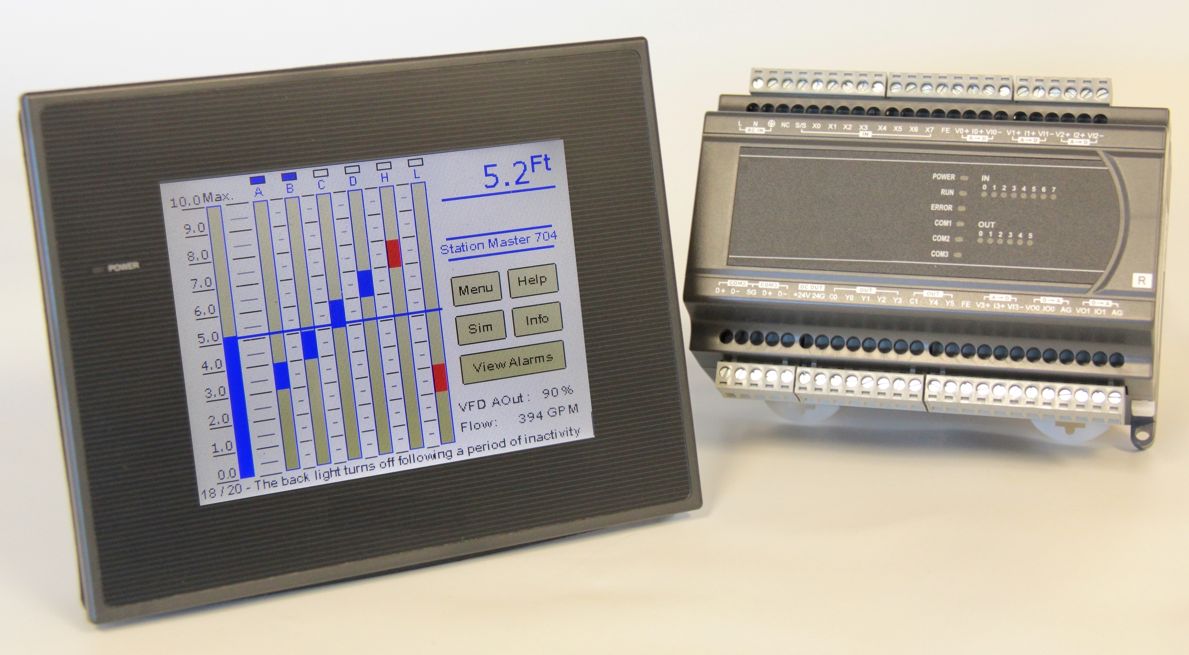
The Station Master 704 provides quadruplex pump control with an intuitive, easy-to-use graphical user interface.
The HMI provides a graphical representation of the
process. The left-most column represents the process level. Subsequent columns represent Pump and Alarm On/Off setpoints. Underlying screens allow the operator to adjust setpoints, select alternation sequences and configure the controller for the specific application.
The DIN-rail-mounted IO Module is typically mounted on the enclosure’s inner panel. The module’s relay outputs provide control for the four pumps and two selectable alarm points. The module’s inputs are user selectable and include: pump running, pump failed, control inhibit and external alarm acknowledge. The primary and secondary (optional) process sensors and a flow sensor (optional) connect to three of the module’s 12-bit analog inputs. The SM704VF provides VFD control via by one of the I/O module’s analog outputs. The second analog output provides a 4-20 mADC output that follows the process level over a 0-100% excursion.
Contegra’s STATION MASTER 704 controller is an Easy-to-See and Easy-to-Set (EZ2 See/EZ2 Set™) automatic duplex pump control and alarm monitoring system.
The STATION MASTER 704 controller is ideal for sewage lift stations, water systems, or other process control applications. The EZ2 See/EZ2 Set™ interface makes installation and operation a simple process. The graphical display shows the current tank level, Pump 1-4 On/Off setpoints, and the High and Low alarm setpoints.
All adjustments, including controller configuration, pump on/off settings, and alarm setpoints are easily accessed via either the main screen’s columnar display or via the main screen’s MENU pushbutton.
EZ2 SEE DISPLAY
The LED backlit HMI provides daylight viewable indication of the current tank level, pump on/off setpoints, and high and low alarm setpoints, along with easily accessible controller setup information (e.g. alternator sequence, pumping direction, etc.)
EZ2 SET ADJUSTMENTS
The TouchPoint™ operator interface leads the operator through the setpoint and configuration selections. The features include setpoint adjustment, convenient selection of the pumping order, pumping direction (i.e. Pump Up/Pump Down), and numerous other easily understood and readily accessible features. This “guided tour” of the controller’s features makes operating the controller as easy as touching the desired setpoint or adjustment and changing the respective setpoint.
With the STATION MASTER controller’s sealed front cover there are no programming switches to move or jumpers to lose. The interface makes setup, adjustment and confirmation of the controller’s operating parameters EZ2 See/EZ2 SetTM.
The controller accepts analog inputs ranging from 4-20 mADC or 0-5 VDC. The Station Master 704 controller is able to easily scale either a calibrated (i.e. 4-20 mADC over 0-10’ excursion) or an uncalibrated input.
A Feature Packed System
Whether dealing with a new installation or retrofitting an existing site, the Station Mater 704 controller provides outstanding control and alarm capabilities.
The TouchPoint™ interface allows the operator to easily select 1st On/ 1st Off, Fixed, or Rotary alternation.
All adjustments and setpoints are stored in permanent memory.
The installing technician sets the controller’s operating range to a value up to a 100.0’ excursion.
The Station Master 704 has an on-board audible alarm and two selectable alarm outputs. The operator may select a number of available alarm conditions to activate the alarm output(s).
Manual level simulation allows the operator to test the controller’s operation and confirm the configuration. Pressing the SIM button activates level simulation. Simulation “safety” is an integral part of the Station Master’s control strategy.
To prevent unauthorized changes to the system’s settings, the HMI’s setpoints and configuration adjustments are protected by multiple security levels.
The Station Master 704’s inputs may be configured as either sinking (i.e. Pull down) or sourcing (i.e. Pull-Up).
I/O features:
- Analog input: 4-20 mA or 0-5 VDC input. The IO module provides 24 VDC for sensor excitation.
- Selectable inputs: Pump Running, Failed, Unavailable, Flow pulse (w/totalization), alarm acknowledge and controller inhibit.
- Discrete Relay Outputs: Pump 1-4 Control and two selectable alarm outputs. All relay outputs are normally open (i.e. open on power failure). Outputs 1-4 share a common return. Outputs 5 & 6 share a second common return. The relays are rated for 2 amps maximum per contact and a maximum of 5 amps per common.
Installation
Externally the HMI is 5.7”H x 7.25”W x 1.7”D . The required door cutout is 5.2”H x 6.78W”.
The IO module is 4” H X 6”W X 3.25”D. All wiring is terminated at removable terminal blocks.
The SM704 includes the serial communication cable that provides communication between the HMI and the IO Module.
Power: HMI— 24 VDC, IO Module — 120 VAC.